
Engineering Capability Showcase: Custom MCU-Programmed Motorcycle LED Tail Light PCBA
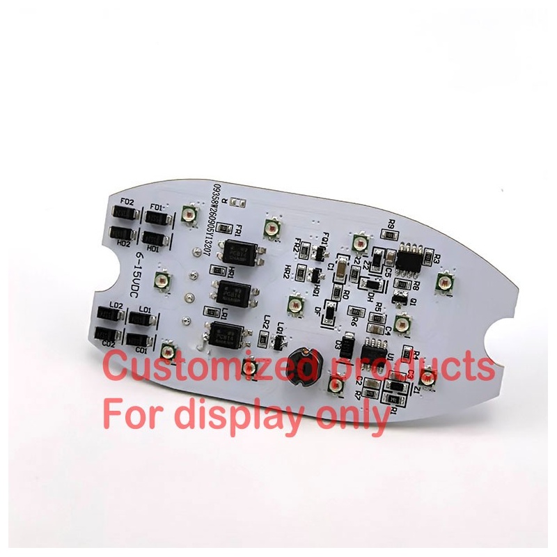
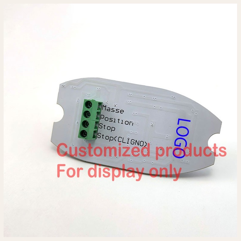
This product represents MIDCARS' turnkey electronic design and PCBA contract manufacturing capabilities specifically engineered for electric scooters, classic motorcycles, and specialized light electric vehicles (LEVs). Built upon an embedded microcontroller (MCU) running dedicated firmware, this assembly seamlessly coordinates multi-tier lighting signals: a low-power running/position light (Position), an intensified braking illumination (Stop), and an auxiliary flasher trigger input (Stop<CLIGNO>) that operates synchronously with the vehicle's onboard flasher relay.
By combining an intelligent non-polarity diode bridge network with a discrete constant-current regulation topology across a wide 6–15VDC operating range, this board eliminates reverse-polarity wiring hazards during vehicle retrofitting while delivering stable, flicker-free luminous performance under fluctuating alternator or battery states. Displayed strictly as a manufacturing capability showcase under client authorization.
MCU-Programmed Multi-Function Operational Logic
Unlike basic resistor-based LED boards, this design integrates an onboard microcontroller to manage priority and transition curves between critical signaling states:
- 1. Running / Tail Marker Mode (Position - Low Brightness): Provides a regulated, glare-free continuous rear marker illumination with optimized power consumption, ideal for vintage 6V magneto systems or modern 12V battery banks.
- 2. High-Intensity Brake Mode (Stop - High Brightness): Instantly transitions all LED arrays to maximum rated luminous output upon brake switch engagement, ensuring commanding daytime stopping visibility.
- 3. Flasher Signal Synchronization (Stop<CLIGNO>): Accepts dedicated input from the vehicle's flasher relay to execute rapid rhythmic pulse signaling, providing enhanced hazard warning or specialized emergency deceleration alerting.
- 4. Non-Polarity Dual Bridge Architecture: Enables foolproof installation where technicians or end-users cannot accidentally damage the MCU or LED diodes through reversed wiring leads.
Custom PCBA Engineering & Manufacturing Scope
1. Firmware & MCU Logic Customization
Custom dimming ratios (PWM duty cycle), strobe/flashing patterns, strobe-then-solid brake sequences, and CAN-bus/LIN communication interfaces designed to your exact software specification.
2. Mechanical Contour & Thermal Substrates
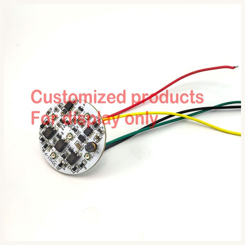
Precision CNC/laser routed board shapes to fit into proprietary tail light housings (oval, boat-shaped, circular, or tiered). Available in high-thermal aluminum MCPCB or multi-layer FR4 substrates.
3. Voltage Platforms & Electrical Hardening
From classic 6V/12V automotive to heavy commercial 24V or high-voltage electric mobility platforms (36V, 48V, 60V, 72V, up to 80VDC). High-voltage TVS suppression shields against motor regenerative spikes.
4. Terminal Blocks & Cable Harnessing
Choose between robust screw terminal blocks (as shown on model 02), automotive-grade quick-disconnect wire harnesses, or potted lead wires with customized pinout and connectors.
Turnkey OEM/ODM Development Workflow
MIDCARS delivers an end-to-end engineering journey for overseas vehicle manufacturers, brand distributors, and custom builders:
- Requirement & Schematic Capture: Analysis of target housing volume, voltage supply, LED photometric standards (ECE/DOT), and MCU signaling sequence.
- PCB Routing & Thermal Simulation: Precision CAD layout optimizing trace current capacities, heat spreading, and EMC shielding.
- Rapid Functional Prototyping: High-speed SMT assembly of engineering samples for bench testing and photometric verification within 7–14 days.
- Reliability & Vibration Validation: Rigorous thermal shock (-40°C to +85°C), high-frequency mechanical vibration, and 100% full-load electrical burn-in testing.
- Automated SMT Mass Production: High-precision pick-and-place lines with in-line Automated Optical Inspection (AOI) to guarantee zero solder bridge defects.